|
* TinkerDifferent *
Retro Computing Community |
| Home | Forums | What's New | Search | Settings |
| Macintosh SE/30 M5119 - Year long troubleshooting battle |
Forums > Vintage Apple > Macintosh > Compact Macs
|
GreenBar0n New Tinkerer East Bay Area, CA -------- Joined: Dec 22, 2025 Posts: 32 Likes: 6 |
Dec 22, 2025 - #1
Hi all,
Really glad to have found this forum recently and specifically the Simasima Repair Guide posted here, much thanks for that! I purchased this SE/30 around this same time last year and recapped every board in the unit, also removed UE10 and reinstalled it, fixing all of the broken traces. UE10 is not pretty, but functional and no bridges. Has +5.05V at pin 35, Reset is working. UE8 was also replaced. But I still get the Simasima pattern. Took a break from this project because I was lost and didn't know how to fix this, then I found the Repair Guide here a couple of weeks ago. This gave me a push to pick this back up and try again. Brief summary of all of the troubleshooting steps taken up until today: Entire Recap of every board - PSU voltages are +12.66V, +5.05V, -11.77V Remove, clean, and reinstall UE10 and UE8 Tone out every single Address and Data line from the CPU and PDS, to the ROM and Memory socket - took forever but all connections are there. Removed all socketed ROM, GAL/PAL chips, DeOxit and clean the chip legs Verify that UE10 ASC/DSC is connected and all of the traces are working according to the Address and Data line Matrix, pages 10-11 in the Redrawn Schematic This brings me to where I'm at currently, the clock signals provided by the Simasima Repair Guide. This is what was measured today: I'm concerned with the C16G clocks not being exact and instead, matching the C16M clocks instead. The E clock is also under speed. But C3M being under speed and also having this strange looking wave pattern has me wondering if this is causing any issues: The Repair Guide doesn't mention what the problem could be, or what to do, in the case that my Clocks aren't exactly right. Can anyone see what I'm doing wrong here? Or where I should look to fix the Clock issue I seem to be having. I have a Reloaded SE/30 V5 board arriving today, in the case I'll need it - but this stock board really doesn't seem to be that bad. Thanks again for this great site and the repair guide! Any help you can provide me going forward, I'll follow the directions to the letter and greatly appreciate it.
Liked by iantm |
|
Nixontheknight Tinkerer -------- Joined: Nov 3, 2021 Posts: 190 Likes: 34 |
Dec 22, 2025 - #2
check the main crystal, maybe something's up with it
|
|
GreenBar0n New Tinkerer East Bay Area, CA -------- Joined: Dec 22, 2025 Posts: 32 Likes: 6 |
Dec 22, 2025 - #3
Where is that exactly, and how would I check it?
Thanks! |
|
Nixontheknight Tinkerer -------- Joined: Nov 3, 2021 Posts: 190 Likes: 34 |
Dec 22, 2025 - #4
it's that metal looking chip towards the middle of the board
|
|
GreenBar0n New Tinkerer East Bay Area, CA -------- Joined: Dec 22, 2025 Posts: 32 Likes: 6 |
Dec 22, 2025 - #5
Are there more crystals than the largest rectangular one? How would I confirm the C3M clock is having problems in this case?
|
|
Nixontheknight Tinkerer -------- Joined: Nov 3, 2021 Posts: 190 Likes: 34 |
Dec 22, 2025 - #6
I think the rest of the signals are generated from one of the chips, but I'm not sure which
|
|
GreenBar0n New Tinkerer East Bay Area, CA -------- Joined: Dec 22, 2025 Posts: 32 Likes: 6 |
Dec 22, 2025 - #7
The 'main' Xtal has 31.334 MHz written on it, that and the C16M 16.667 Mhz clock is perfectly in speed with the guide. I'm having trouble with 3.9MHz specifically.
Y1 and Y2 are also part of the clock signals? How are the clocks divided in to the slower speeds? Thanks. EDIT: Setup my scope trigger better this time, but it still seems jittery and under speed, should be 3.9 MHz according to C3M.
|
|
GreenBar0n New Tinkerer East Bay Area, CA -------- Joined: Dec 22, 2025 Posts: 32 Likes: 6 |
Dec 22, 2025 - #8
Setting aside the clock signals for the moment, I moved on to the Reset circuit, I definitely have an issue here:
UB11 pin5 is fine but pin6 only drops to about 4V, never goes full 0V - 0.80Mv. RP7 pin2 stays at 5V. This seems like the most significant issue I've found so far. Need to figure out why this happening and how to fix it. Any recommendations or insights to this?
|
|
GreenBar0n New Tinkerer East Bay Area, CA -------- Joined: Dec 22, 2025 Posts: 32 Likes: 6 |
Dec 23, 2025 - #9
Was measuring RP7 pin7, not pin2, RP7 pin2 does go to 0V with Reset. RP7 is good, my mistake.
Added sockets for UB10 and 11, the Sony Sound chips. According to the schematic: Pin5 is Reset, but Pin6 is something called VSNS: When I test pin6 on both UB10 and 11, it only drops to 3.9V with Reset. Is pin6 really supposed to be 0V when Reset is pushed?
|
|
GreenBar0n New Tinkerer East Bay Area, CA -------- Joined: Dec 22, 2025 Posts: 32 Likes: 6 |
Dec 23, 2025 - #10
Tried the ROM/CPU walk the bus test and I don't get a solid square wave from any of the pins, the wave form is a mess. Suspecting a bad CPU.
Is there any way to tell a CPU is bad without another to test with? |
|
GreenBar0n New Tinkerer East Bay Area, CA -------- Joined: Dec 22, 2025 Posts: 32 Likes: 6 |
Dec 23, 2025 - #11
Looking for some advice on where to go next with this. The problem I'm having is that the CPU will not walk the bus.
No matter what pin I'm measuring in the ROM slot, there is no clean square wave. With or without the CPU inserted, I get the same result, no square wave. The Simasima repair guide mentions that the CPU could be bad, though it's not typical. But with not one single Address line in the ROM slot producing a solid square wave, I'm out of places to look. I didn't want to build a Reloaded board only to find out my CPU was bad. Is there anything other than a bad CPU that could be causing the problem I'm experiencing here?
|
|
Nixontheknight Tinkerer -------- Joined: Nov 3, 2021 Posts: 190 Likes: 34 |
Dec 24, 2025 - #12
SE/30s are picky about their memory, maybe try swapping the memory?
Liked by GreenBar0n |
|
GreenBar0n New Tinkerer East Bay Area, CA -------- Joined: Dec 22, 2025 Posts: 32 Likes: 6 |
Dec 24, 2025 - #13
I have two different 4Mb sets of RAM that came with this SE/30. I was using the Ti set in the previous pictures. I also have two working SE's here that I tested the RAM in,
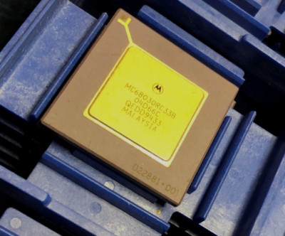
I put the set on the right in just now and ran the scope. It's the same with or without a CPU in this board, no clean square wave on any ROM slot. Just got an email saying my ebay offer was accepted for a NOS MC68030RC33B CPU, in Long Beach, CA. I'm in the East Bay of CA, so I should see the new CPU pretty quickly. For $30 + shipping, it's worth the gamble, as this board looks to be in order and works with all other tests besides the CPU. MC68030RC33B MC68030 MOTOROLA GOLD PGA VINTAGE NOS COLLECTIBLE QTY-1 | eBayMC68030RC33B MOTOROLA. THIS IS FOR 1 PIECE.
www.ebay.com
Received the Reloaded V5 Purple board yesterday. Looks like the purple boards sold out, the black V5 boards are all that's left.
Liked by muse |
|
muse Tinkerer Oz -------- Joined: Nov 3, 2025 Posts: 41 Likes: 30 |
Dec 24, 2025 - #14
What are the address lines doing from the 68030 ?, if they are stuck high then that could confirm your suspicions on a bad reset circuit.
You'd want to confirm that the signal is reaching the CPU by probing the 68030's rst and halt line inputs, these are active low signals. So it should toggle from low for around 100ms then stay high, then you should see address and data activity on the bus. Liked by GreenBar0n |
|
GreenBar0n New Tinkerer East Bay Area, CA -------- Joined: Dec 22, 2025 Posts: 32 Likes: 6 |
Dec 24, 2025 - #15
The Reset pin F12 on the CPU is functional, it goes from +5.05V to 0 - 0.80Mv when S1 is pressed.
The only Reset pins that were questionable from the Simasima Repair Guide, were the UB10 and 11 Sony Sound chip pin6's, pin5's can Reset +5.05V to 0 - 0.80 Mv. I can't see the Reset being an issue at this point. The scope should show clear and clean square waves on Address lines A2-A31, I get that messy wave form shown above, Are you saying I should use the DMM instead of the scope to look for +5.05V at A2, for example, in the ROM slot? A2 should show +5.05V for 100ms then go low to demonstrate it works correctly? |
|
GreenBar0n New Tinkerer East Bay Area, CA -------- Joined: Dec 22, 2025 Posts: 32 Likes: 6 |
Dec 24, 2025 - #16
I used the DMM to look at the ROM slot pins, they are all over the place in voltage, very few are always stuck at +5.05V, but nearly all of them respond to the S1 Reset button being pressed.
|
|
muse Tinkerer Oz -------- Joined: Nov 3, 2025 Posts: 41 Likes: 30 |
Dec 24, 2025 - #17
The scope is the right tool.
I also can't see a problem with the waveforms you took, its normal to see some noise in those readings especially at 1v divisions where the jitter is more pronounced. The comparison shot appears to be sampled using 2v divisions, noise is still present but isnt going to be as obvious Liked by GreenBar0n |
|
GreenBar0n New Tinkerer East Bay Area, CA -------- Joined: Dec 22, 2025 Posts: 32 Likes: 6 |
Dec 24, 2025 - #18
Hoping the CPU is what's bad. The UE10 DSC was really bad on this SE/30, the voltage line broke and probably four other lines were severed as well. Not sure if that could kill a CPU, but anything is possible. I watch the CayMac repair videos and he happened upon a bad SE/30 CPU a few months ago. Should know pretty soon. Thanks for your help @muse!
Another ebay seller just accepted my offer for a genuine and 100% complete Apple Techstep, wasn't expecting to get a piece of history like this today, for $500. Wanted one of the CayMac reproductions but I think he's done making those. Excited about this but realize I have to get to at least a SadMac stage to make this work. This will come in handy if I need to build the Reloaded board.
|
|
muse Tinkerer Oz -------- Joined: Nov 3, 2025 Posts: 41 Likes: 30 |
Dec 26, 2025 - #19
Those gold top Motorola PGA packages are fairly robust. Ive never come across a bad one yet or seen one fail, but to be fair I was predominately an Amiga user where cheaper variants were used except on expensive accelerator boards which I could not even afford anyway :)
Dead machines can hide many faults so I would be searching for a confirmed working SE/30 board to test your suspected bad parts in by substitution until ( rom board, video mask rom, 68030, ram sticks ..etc) you reproduce the exact same fault...maybe not if the fault is somewhere else on the board like a bad trace, ASIC or logic ic. Liked by GreenBar0n |
|
GreenBar0n New Tinkerer East Bay Area, CA -------- Joined: Dec 22, 2025 Posts: 32 Likes: 6 |
Dec 26, 2025 - #20
I feel like I keep repeating myself, because I've replied to two different forums, and many threads trying to narrow down where the problem is coming from.
A working SE/30 board is hard to come by these days, I'd have to buy a $500+ working SE/30 to get an example to follow. The immediate and most pressing issues are the clock values and the CPU not walking the bus according to the Simasima Repair Guide. The most current problem I could really use an answer for, is if the Y3 Xtal is supposed to have matching wave forms on both of its legs, like Y1 does. Y3 is close to my UE10 that had to be removed, cleaned and (4) traces repaired. My Y3: Y3 leg farthest from UE10: Y3 leg closest to UE10: I'm wondering if the Y3 wave forms should be identical to each other. This has been the hardest restore project I've done, Commodore SX-64 and 128 were far easier :)
|
| Page 1 of 2 | Next > | Last >> |
| Home | Forums | What's New | Search | Bookmarks | RSS | Original | Settings |
| XenForo Retro Proxy by TinkerDifferent.com |
![[Image: www.ebay.com]](/proxy_image?url=https://i.ebayimg.com/images/g/ZvIAAOSwFxBlsym5/s-l400.jpg)