|
* TinkerDifferent *
Retro Computing Community |
| Home | Forums | What's New | Search | Settings |
| Color Classic Troubles |
Forums > Vintage Apple > Macintosh > Compact Macs
|
TechnikTobi New Tinkerer Austria -------- Joined: Oct 1, 2025 Posts: 10 Likes: 4 |
Oct 2, 2025 - #1
Hi everyone! A few years ago I got a Color Classic that didn't work properly (can't recall the exact symptoms at that point - again, it has been a while...). So I performed the obvious operations: Recapping the logic board with Tantalum capacitors and the more "error prone" caps from the analog board as lined out by @Branchus. At that point I got the CC to boot up to the boot-media-question-mark (original HDD tested & declared dead, no replacement yet). However, the machine didn't seem to make any attempts at reading a floppy when inserted. The question mark kept flashing, the cursor did move but no noise whatsoever from the floppy drive (already did a service on that, tested it and works). Also in some cases, nothing happened at all, no life after switching on power and pressing the boot button from the keyboard (tried different keyboards, all work on other machines). That is where I left the project some time ago.
A week ago or so I stumbled upon the component upgrade video by @JDW and the tip for using an even cooler running diode. Inspecting the diodes on my CC's AB showed the same discoloration on the board, so I replaced the two diodes DL21/22 with a DOI-201 packaged 1N5355B + a copper heatsink (looks a bit weird, I admit, but should get the job done. The two copper plates are held together at the top so that they don't vibrate using a bit of heat shrink that is additionally hardened with a bit of super glue), RL22, RL62, RF11, DF2 and the surrounding electrolytic capacitors that haven't been replaced yet (just in case they were affected by the heat - I know, not really necessary, but if I am already working on that area...). Unfortunately this is not enough: There is a picture (although with a strong blue tint that doesn't really come across on the video I uploaded and a bit of a geometric distortion at the top and bottom, though I suspect that is more of an adjustment issue) and the CC tries to boot but shuts down/looses power after less than a minute (see video). Sometimes it gets to the boot-media-question-mark, but not always. Putting in a floppy doesn't seem to make a difference, no audible attempt at trying to read anything from that. With a bit of help from my dad we were able to read the voltages on the HDD power connector (as there isn't a disk in there) in the short time it powers on but nothing out of the ordinary there either (just shy of 12V and 5V). This is where I'm currently stuck and need help/advice on what to take a look at next. I still suspect that the analog board is the (main) culprit here as the CC gets to the point where I can see and move the cursor, so I don't think its the logic board (also, the blue tint of the image) - on the other hand, the floppy drive showing no signs of life could either be a power issue there or a failure of the floppy controller on the LB? But then, why would this cause the machine to suddenly lose power? Any help or advice is greatly appreciated! Please feel free to ask me for any additional information required to troubleshoot this in case I missed something!
|
|
JDW Administrator Japan -------- Joined: Sep 2, 2021 Posts: 2,536 Likes: 1,983 |
Oct 2, 2025 - #2
@TechnikTobi
Welcome to TinkerDifferent! Congrats on doing the Beefy Component Upgrade and for heat sinking your DO-201 Zener Diode! I enjoyed looking at your photos. Should be interesting to see how long the superglue holds that heatshrink atop those heatsinks. Anyway, I'm glad you used an insulator (heat shrink tubing) and not a piece of metal. :) I don't think people will solder a deal short across their Zener, but you never know what people will do at times. In regards to your power instability, it's important to know that no fluid-filled electrolytic capacitor has eternal life. Any such cap more than 25 years old and especially those used in hot conditions like the CC Analog Board needs to be replaced. Yes, even the largest cap on that board too. They ALL must be replaced with 105*C rated capacitors to ensure you get a reasonable life from them. I also suggest making sure the LEAD SPACING is correct for replacement caps too, especially for the big ones, because you don't want those sitting up on their legs. The caps surrounding the DL21/DL22 diode area absolutely must be replaced because they have had the hottest heat exposure over the years. Doing that alone may resolve the sudden shutdown problem. And if it doesn't, then it's time to take a closer look with a magnifying glass at traces on the solder side and any burned components, especially transistors on the component side. All connectors and the flyback and power switch need to have their solder reflowed. This is an absolute must. Could be that alone is the main problem, and as the machine heats up, a cracked solder joint comes apart enough that the machine loses power. Go over all solder joins with a magnifying glass. I did that on my Analog Board. Yes, it is time consuming but necessary. Once your machine remains on without issue, you can then do the CRT Adjustments at back, in accordance with my video on that here... I look forward to hearing how it goes! |
|
TechnikTobi New Tinkerer Austria -------- Joined: Oct 1, 2025 Posts: 10 Likes: 4 |
Oct 2, 2025 - #3
Hi, thanks for the quick reply! Yes, I'll eventually update on how this heat shrink tubing construct holds up over time.
Okay, so what I get from this is that for now I should just replace all caps that are still original - is there anything else I could/should replace as a precautionary measure? For example, upon further inspection, I noticed some similar heat-related discoloration of the board around DP6 & RP15 (next to the big 330µF/400V capacitor CP30) and RP8 & RP23 (also adjacent to CP30). Any experience on replacing those? I also read about others with failing RIFAs, optocouplers, ... What about those? In the meantime I'll reflow the solder joints... Any advice on how to do that with all the SMD components on the solder side? |
|
JDW Administrator Japan -------- Joined: Sep 2, 2021 Posts: 2,536 Likes: 1,983 |
Oct 2, 2025 - #4
Here's a high resolution photo of my board prior to my Beefy Component Upgrade... [Image: Analog-Board-Top-JDW.jpg] And here's a hi-rez photo of the bottom of the board, after the beefy component upgrade, but only part way through the 84V 13" Hi Resolution Mod... [Image: Analog-Board-Btm-JDW.jpg]
|
|
TechnikTobi New Tinkerer Austria -------- Joined: Oct 1, 2025 Posts: 10 Likes: 4 |
Oct 2, 2025 - #5
Thanks for the high-res images! Comparing them to images I took a few days ago prior to the component upgrade there is definitely some discoloration on both sides of the board and not just some dirt (though you are right that I should also go over the entire board with some cotton swabs and IPA).
|
|
JDW Administrator Japan -------- Joined: Sep 2, 2021 Posts: 2,536 Likes: 1,983 |
Oct 2, 2025 - #6
Very interesting. Thank you for the photos. Certainly looks like DP6 and RP15 have been compromised due to heat. But resistors RP23 and RP8 are raised up off the board, and yet the board directly under them is charred. Very odd.
Not sure if he'll reply, but I'd like to ask @techknight if he's seen charring in that area before. He has lots of experience repair these boards, so it could be something he has seen. I will tag @Kay K.M.Mods as well. I myself only have the one Color Classic, so I am only experienced on the board I have in front of me. Also, @Paolo B , would you happen to have any thoughts? Liked by TechnikTobi |
|
Paolo B Tinkerer Switzerland -------- Joined: Nov 27, 2021 Posts: 303 Likes: 182 |
Oct 2, 2025 - #7
I have three CCs, each of them at a different mod level. Besides the
|
|
Paolo B Tinkerer Switzerland -------- Joined: Nov 27, 2021 Posts: 303 Likes: 182 |
Oct 2, 2025 - #8
The very bluish tint during the few secs the machine is alive are surely speaking for some issue in the video circuitry. First off, though, I would try to disconnect the hard drive and the floppy and see if it remains alive, as the timing of the shut down seems to be quite consistent with the one at which the OS should be loaded. |
|
JDW Administrator Japan -------- Joined: Sep 2, 2021 Posts: 2,536 Likes: 1,983 |
Oct 2, 2025 - #9
Solder joins for these two components look "factory" done...
But these solder joints look either compromised or someone desoldered them and resoldered without flux... The problem is that there is no Schematic for the CC Analog Board, so problem (burned) components need to be traced by hand to see where the current is coming from and where it is going. In other words, it's more than the aforementioned 4 components possibly being bad. Something caused them to burn. In the case of DP21 and DP22, we know the reason. It's bad to use two Zeners in parallel, because one could heat more than the other. And they both were only rated for about 1.25W, originally. And they were clearly shunting more current to ground than they could handle without being heatsinked. Even so, the AMOUNT OF CURRENT running through them was the issue. Had there been less current flow shunted through D21 and D22, they wouldn't be charring boards. In like manner, the reason for excessive current flow through the 4 aforementioned components needs to be determined. And the mystery of why the board is charred beneath two very large resistors (RP23 and RP8) which are lifted up and off the board needs to be determine. Is it really possible for those two huge resistors to get hot enough that high up off the board to char the board beneath them? That is really odd!
|
|
techknight Moderator North Carolina -------- Joined: Dec 2, 2021 Posts: 94 Likes: 94 |
Oct 3, 2025 - #10
These boards all need fully resoldered, and fully recapped now. The solder joints have gotten atrocious on these boards. Also de-oxit the middle cable that goes between the front and the middle, which carry the video signals. As well as resoldering all of that. That usually takes care of most problems, the rest need adjusted out on the rear. Lastly, the opto-couplers are a common failure point on these causing intermittent power/shutoff scenarios. Liked by JDW |
|
TechnikTobi New Tinkerer Austria -------- Joined: Oct 1, 2025 Posts: 10 Likes: 4 |
Oct 3, 2025 - #11
Thanks for all the input!
Regarding the HDD/Floppy: There is no HDD currently in the CC, and the floppy drive just remains dead silent. Though I have to correct myself, as I didn't look close enough. The machine gets to the "can't boot from this device"-icon with a "X", not the "can't find boot device" with a "?". But I'll try again with the floppy drive removed (and put that in my non-color classic to check if it works there, even though it tested o.k. last time after I serviced it).
Liked by Paolo B |
|
JDW Administrator Japan -------- Joined: Sep 2, 2021 Posts: 2,536 Likes: 1,983 |
Oct 3, 2025 - #12
Separately from that, I modified your photo so it would perfectly overlay might photo, and you can see the board revision differences below... Note the fat trace at the bottom of RP23 and RP8. My board must be newer than yours because mine has extra solder applied to that trace, either for better currently handling or better cooling or both.
Liked by Paolo B |
|
TechnikTobi New Tinkerer Austria -------- Joined: Oct 1, 2025 Posts: 10 Likes: 4 |
Oct 4, 2025 - #13
Some progress: I now went basically over all solder joints (except for SMD stuff) and now the image is "stable" in the sense that it now longer flickers between perfect gray and purple and has no longer the geometric distortion at the top and bottom [face-with-party-horn]
However, the loss-of-power-problem after around a minute or two still persists. I removed the floppy drive as suggested by @Paolo B but that didn't change anything (still have to test that in my non-color classic). Also, it seems to me that if I power it on with the switch on the back for a few minutes and then try to boot, it stays alive longer than booting immediately after switching on power - but perhaps I'm imagining things. Similarly, there is this weird noise when the CC is switched on (see video - though it is quiet), I guess from a coil that's vibrating? I forgot what this thing/CRTs in general without any fans or anything are supposed to sound like...).
I see. Well, I don't have a thermal camera, but I do have a multimeter that is able to measure temperature! I did some basic measurements, with the power on the backside switch turned on but not having booted or anything. And what I get is this: - RP8 (15k) gets to ca. 75-85*C - RP23 (22k) gets to ca. 95-105*C (see image) - Ambient temperature ca. 26*C both are coolest at the center of their body and get warmer towards the edges where the legs come out. I didn't want to touch them with my probe (as that is also made out of metal) but my guess is that the legs will have a similar temperature. The resistor right next to both of them (RP37) stays cool at ca. 40*C. Do you have measurements with your thermal camera to compare that to?
Yeah, mine is a rev. B board. I did add some additional wire (without insolation) along that trace between RP8+23 and LP2 for additional current handling and head dissipation. Don't know if that is going to make any difference but it couldn't hurt either. Anyway, I still don't know what to do about RP15+DP6. For RP8+23 my next step is to desolder one of their legs to measure them and if they are within tolerances leave them as they are for now despite the heat marks. Replacing them won't solve the root cause of why they get so hot in the first place, same with RP15. And, without knowing what DP6 actually is, I'll have to leave that also as it is and hope that replacing the remaining caps (and the optocouplers) solves my power issue...
Liked by JDW |
|
JDW Administrator Japan -------- Joined: Sep 2, 2021 Posts: 2,536 Likes: 1,983 |
Oct 4, 2025 - #14
You can see all the hot areas of the Analog Board and some temps from one of those resistors here: But honestly, even at 105*C, those resistors are not super hot. The 3W and 5W resistors are made to get hot. They can get upwards of 200*C actually, in accordance with their datasheets, which is hotter than diodes are allowed to get (usually 150*C max.). I really wish thermal cameras were cheaper so I could recommend a cheap one for you, because that's the fast-track to nailing down excessively hot areas of any board. Sadly, the thermal camera makers really keep prices high. Not sure why because it's not like the tech came out yesterday. Supply and demand, I guess. Tariffs have made them too expensive: Amazon.com
www.amazon.com
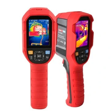
I got mind for around this price back in 2023 (and I paid separately for the close-up lens): UNI-T UTi260B 256*192 Pixel Infrared Thermal Imager -20~550*C Industrial Thermal Imaging Camera Handheld USB Infrared ThermometerOnly US$257.99, buy best uni-t uti260b 256*192 pixel infrared thermal imager -20~550*c industrial thermal imaging camera handheld usb infrared thermometer sale online store at wholesale price.
[Image: www.banggood.com]
www.banggood.com
I've read about iPhone add-ons, but they tend to be lower resolution, and when you consider that even my 260B is already pretty low resolution as it is, having something lower really isn't that great. But the 260B is great because if you have a Windows PC, you can tether it to the computer and made videos of your measurements on the computer side. The 260B has a trigger that, when pressed, lets you take screenshots of what is shown on the 260B's LCD at any given time. Great for capturing shots of specific components that are way too hot. The 260B is also quite accurate too. You just have to avoid shiny metal parts which can give false readings, but for black bodies and for resistors and transformers, it works great.
I could hear it clearly when watching your video on my iPhone, but when watching on my 16" MBP, I had to crank up the volume to hear it. I am not detecting the same sound on my Rev.C board, but sadly, I have zero experience with other A.B. revisions, which again is why I need to defer to more experienced folks like @techknight , who has touched many types of boards and perhaps has heard all the sounds. All I can say is that when I first switch on the main power at back, I hear a brief hum from the machine, which dies down to inaudible, quickly. If I later press the Power Key on the keyboard to boot, then I hear the static-like sound of the CRT turning on, HDD spinning up, and I might hear a little while for a time, but as the machine heats up, the sounds largely go away, especially with the case on. The case fan tends to drown them out, I mean. So in comparison to my Rec. C board, your sound appears odd to me, unless your sound is truly hard to hear in the first place, in which case it may be normal. But if it sounds loud even with the case on, maybe it is a sign of a problem? Not sure. I'm going to tag @Kay K.M.Mods because he, like TechKnight, has touched a lot of Analog Boards and should know the right and wrong sounds. Hopefully he will add his thoughts to this thread at some point.
But that DP6... Man, I'm really sorry but I have no idea. Is it a Zener? Schottky? Silicon Diode? Not sure what it is. Again, I need to defer to TechKnight and Kay, as one of them may know.
|
|
TechnikTobi New Tinkerer Austria -------- Joined: Oct 1, 2025 Posts: 10 Likes: 4 |
Oct 9, 2025 - #15
So I desoldered DP6 to get a closer look and the packaging says: PH BYD34J. Good news: Googling that name gives me a data sheet. Bad news: it is no longer available - though I want to replace it with something more capable anyway, similar to the DL21/22 mod. However, I'm not sure on how to pick a proper replacement part. What are okay-ish deviations for what properties? Is it for example okay to use a replacement with a higher IF value? Lower? Does it have to be an exact match like a capacitor's capacitance? Liked by JDW |
|
techknight Moderator North Carolina -------- Joined: Dec 2, 2021 Posts: 94 Likes: 94 |
Oct 9, 2025 - #16
The way I do it is look at the datasheet and see the recovery raitings, the voltage/current raitings and i use those details as filters to pick a new one on Mouser/Digikey. It is a fast recovery rectifier, aka shottky diode. According to the datasheet, its a 600V 1.8A Shottky. you can probably get away with a 600V 2A. Works 99% of the time. |
|
TechnikTobi New Tinkerer Austria -------- Joined: Oct 1, 2025 Posts: 10 Likes: 4 |
Oct 9, 2025 - #17
Liked by JDW |
|
techknight Moderator North Carolina -------- Joined: Dec 2, 2021 Posts: 94 Likes: 94 |
Oct 9, 2025 - #18
Considering the application, it would likely work fine
Liked by JDWandTechnikTobi |
|
TechnikTobi New Tinkerer Austria -------- Joined: Oct 1, 2025 Posts: 10 Likes: 4 |
Oct 15, 2025 - #19
Update: So I've now recapped the entire AB and at first it seemed like the CC is able to stay powered on much longer than before, manually killed power after ~10 minutes to put the Floppy drive back in (which I hadn't installed back yet after confirming that it, indeed, works). So I took the AB out, put the drive in, put the AB back in and... nothing. The power goes out basically immediately, no chime, the power LED doesn't even stay on for a second, then the CRT sizzles like it does when it's powered off.
So I took the AB out again, looked at it carefully, soldered some joints that didn't look super nice but should have been fine, just so that I changed something. Put the AB back in and I'm basically back to where I was prior to the last recapping session: Chime, screen goes on, system gets to the point of flashing the x-marked-disk-symbol, cursor can be moved by the mouse, system suddenly collapses after 1-2 minutes. I haven't changed the DP6 diode yet because, to my mind, a diode either works or is dead and doesn't suddenly decide to malfunction, only for it to work again next time. I have the spare I picked together with @techknight just in case someone has an explanation for why I am wrong. Anyway, next I remembered that the CC should behave differently when the LB is removed, so that's what I tried next: LB out, back cover with fan on, switch on and... the fan does spin but definitely not at a constant speed (see video). After a few seconds a new noise came up. At first I thought it was a cable or something that touched the fan blade or something that may have been stuck in there. Back cover off again, looking at the fan it seems perfectly fine, so (with the LB still out) I switched it on again and the new noise was still there (see other video). Weird. As a sanity check I put the LB back in and the behavior was back to before, the new noise was gone. LB out again, new noise is back. I'm running out of ideas at this point... |
|
JDW Administrator Japan -------- Joined: Sep 2, 2021 Posts: 2,536 Likes: 1,983 |
Oct 15, 2025 - #20
I've heard some rear case fan speed instability on my CC as well, but nothing else is wrong so I've just learned to live with it. No clicking sound though and my fan may be a tad more stable than yours.
I know this doesn't help you at all, but just adding what relevant experience I have with the fan. SUPPLEMENTARY INFO: MY FAN: Noctua NF-A8 PWM 80x25mm (full speed, no low-noise adapters used) USAGE CONDITION: Slight fan speed instability confirmed when using the 68.4V VGA Mod and the 84V 13" Hi-Rez Mod. I cannot remember if there was fan instability with the CC in its stock condition. Liked by TechnikTobi |
| Page 1 of 2 | Next > | Last >> |
| Home | Forums | What's New | Search | Bookmarks | RSS | Original | Settings |
| XenForo Retro Proxy by TinkerDifferent.com |
![[Image: Analog-Board-Top-JDW.jpg]](/proxy_image?url=https://tinkerdifferent.com/data/attachments/23/23458-e2ab96040e2e0c762003ea91fa535421.jpg)
![[Image: Analog-Board-Btm-JDW.jpg]](/proxy_image?url=https://tinkerdifferent.com/data/attachments/23/23459-4ae4445ba8f457d8c5cfbd052975cf1c.jpg)
![[Image: www.banggood.com]](/proxy_image?url=https://imgaz3.staticbg.com/thumb/view/oaupload/banggood/images/37/93/5673c9fc-a17b-4865-94a3-7393bdcf3125.jpg.webp)